Voltmeter
Contents
Key Stage 3
Meaning
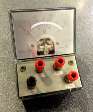
A picture showing an analogue voltmeter.
A voltmeter is a measuring device used to measure the potential difference between two points in a circuit.
About Voltmeters
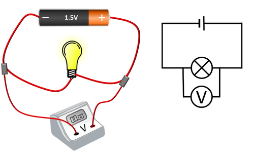
- Voltmeters are added in parallel to components in a circuit to find the potential difference between two points.
- An ideal voltmeter has infinite resistance because otherwise adding an voltmeter to a circuit would change the Potential Difference between two points.
- Voltmeters can be analogue with a needle pointing to numbers on a dial or it can be digital with a number display.
| A voltmeter placed in parallel with a bulb. |
Key Stage 4
Meaning
A voltmeter is a measuring device used to measure the potential difference between two points in a circuit.
About Voltmeters
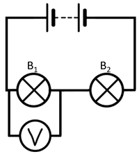
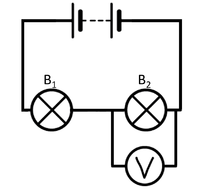
- Voltmeters are added in parallel to components in a circuit to find the potential difference between two points.
- An ideal voltmeter has infinite resistance because otherwise adding an voltmeter to a circuit would change the potential difference between the two points.
- Voltmeters can be analogue with a needle pointing to numbers on a dial or it can be digital with a number display.
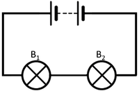
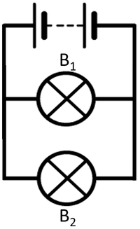
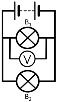
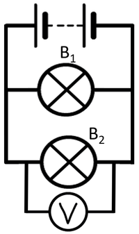
| To measure the potential difference across bulb 1 the voltmeter must be placed in parallel with bulb 1. | To measure the potential difference across bulb 2 the voltmeter must be placed in parallel with bulb 2. |
| To measure the potential difference across bulb 1 the voltmeter must be placed in parallel with bulb 1. | To measure the potential difference across bulb 2 the voltmeter must be placed in parallel with bulb 2. |
| In this case both voltmeters will give the same measurement because the components themselves are in parallel. | |
References
AQA
- Voltmeter, pages 52-3, 56, GCSE Physics; Student Book, Collins, AQA
- Voltmeters, page 239, GCSE Combined Science; The Revision Guide, CGP, AQA
- Voltmeters, page 41, GCSE Physics, Hodder, AQA
- Voltmeters, page 52, GCSE Physics; Third Edition, Oxford University Press, AQA
- Voltmeters, pages 25, 106, GCSE Physics; The Revision Guide, CGP, AQA
- Voltmeters, pages 293, 296, GCSE Combined Science Trilogy 1, Hodder, AQA
- Voltmeters, pages 60, 61, 235, GCSE Combined Science Trilogy; Physics, CGP, AQA
- Voltmeters, pages 62, 63, 331, GCSE Physics; The Complete 9-1 Course for AQA, CGP, AQA
- Voltmeters; calibration of, page 316-17, GCSE Combined Science Trilogy 1, Hodder, AQA
- Voltmeters; calibration of, pages 64-5, GCSE Physics, Hodder, AQA
- Voltmeters; circuit symbol, page 38, GCSE Physics, Hodder, AQA
Edexcel
- Voltmeters, page 143, GCSE Physics, Pearson Edexcel
- Voltmeters, pages 186, 210, GCSE Combined Science; The Revision Guide, CGP, Edexcel
- Voltmeters, pages 220, 338, 339, GCSE Physics, CGP, Edexcel
- Voltmeters, pages 73, 106, GCSE Physics; The Revision Guide, CGP, Edexcel
