Difference between revisions of "Voltmeter"
(→Key Stage 4) |
|||
| Line 23: | Line 23: | ||
: An ideal [[voltmeter]] has infinite [[Electrical Resistance|resistance]] because otherwise adding an [[voltmeter]] to a [[circuit]] would change the [[Potential Difference|potential difference]] between the two points. | : An ideal [[voltmeter]] has infinite [[Electrical Resistance|resistance]] because otherwise adding an [[voltmeter]] to a [[circuit]] would change the [[Potential Difference|potential difference]] between the two points. | ||
: [[Voltmeter]]s can be [[Analogue Voltmeter|analogue]] with a needle pointing to numbers on a dial or it can be [[Digital Voltmeter|digital]] with a number display. | : [[Voltmeter]]s can be [[Analogue Voltmeter|analogue]] with a needle pointing to numbers on a dial or it can be [[Digital Voltmeter|digital]] with a number display. | ||
| + | |||
| + | {| class="wikitable" | ||
| + | |+Using a voltmeter on components in series. | ||
| + | |- | ||
| + | |[[File:CircuitDiagramBatteryBulbBulbSeries.png|center|200px]] | ||
| + | |[[File:CircuitDiagramBatteryBulbBulbSeries.png|center|200px]] | ||
| + | |- | ||
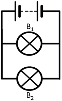
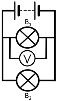
| + | | style="height:20px; width:200px; text-align:center;" |To [[measure]] the [[Potential Difference|potential difference]] across bulb 1 the [[voltmeter]] must be placed in [[Parallel Circuit|parallel]] with bulb 1. | ||
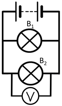
| + | | style="height:20px; width:200px; text-align:center;" |To [[measure]] the [[Potential Difference|potential difference]] across bulb 2 the [[voltmeter]] must be placed in [[Parallel Circuit|parallel]] with bulb 2. | ||
| + | |- | ||
| + | |[[File:CircuitDiagramBatteryBulbVoltmeterBulbSeries.png|center|200px]] | ||
| + | |[[File:CircuitDiagramBatteryBulbBulbVoltmeterSeries.png|center|200px]] | ||
| + | |} | ||
| + | |||
| + | {| class="wikitable" | ||
| + | |+Using a voltmeter on components in parallel. | ||
| + | |- | ||
| + | |[[File:CircuitDiagramBatteryBulbBulbParallel2.png|center|200px]] | ||
| + | |[[File:CircuitDiagramBatteryBulbBulbParallel2.png|center|200px]] | ||
| + | |- | ||
| + | | style="height:20px; width:200px; text-align:center;" |To [[measure]] the [[Potential Difference|potential difference]] across bulb 1 the [[voltmeter]] must be placed in [[Parallel Circuit|parallel]] with bulb 1. | ||
| + | | style="height:20px; width:200px; text-align:center;" |To [[measure]] the [[Potential Difference|potential difference]] across bulb 2 the [[voltmeter]] must be placed in [[Parallel Circuit|parallel]] with bulb 2. | ||
| + | |- | ||
| + | |[[File:CircuitDiagramBatteryBulbVoltmeterBulbParallel.png|center|200px]] | ||
| + | |[[File:CircuitDiagramBatteryBulbBulbVoltmeterParallel.png|center|200px]] | ||
| + | |- | ||
| + | | style="height:20px; width:200px; text-align:center;" colspan = "2"|In this case both [[voltmeter]]s will give the same [[measure]]ment because the [[Electrical Component|components]] themselves are in [[Parallel Circuit|parallel]]. | ||
| + | |} | ||
Revision as of 14:16, 25 February 2019
Contents
Key Stage 3
Meaning
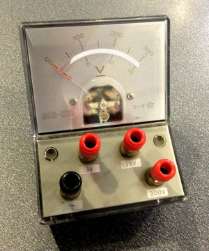
A picture showing an analogue voltmeter.
A voltmeter is a measuring device used to measure the potential difference between two points in a circuit.
About Voltmeters
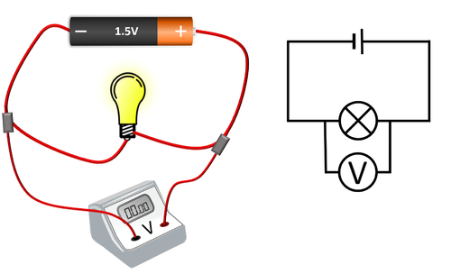
- Voltmeters are added in parallel to components in a circuit to find the potential difference between two points.
- An ideal voltmeter has infinite resistance because otherwise adding an voltmeter to a circuit would change the Potential Difference between two points.
- Voltmeters can be analogue with a needle pointing to numbers on a dial or it can be digital with a number display.
| A voltmeter placed in parallel with a bulb. |
Key Stage 4
Meaning
A voltmeter is a measuring device used to measure the potential difference between two points in a circuit.
About Voltmeters
- Voltmeters are added in parallel to components in a circuit to find the potential difference between two points.
- An ideal voltmeter has infinite resistance because otherwise adding an voltmeter to a circuit would change the potential difference between the two points.
- Voltmeters can be analogue with a needle pointing to numbers on a dial or it can be digital with a number display.
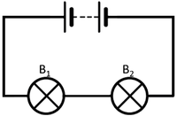
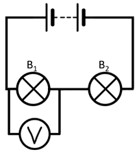
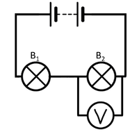
| To measure the potential difference across bulb 1 the voltmeter must be placed in parallel with bulb 1. | To measure the potential difference across bulb 2 the voltmeter must be placed in parallel with bulb 2. |
| To measure the potential difference across bulb 1 the voltmeter must be placed in parallel with bulb 1. | To measure the potential difference across bulb 2 the voltmeter must be placed in parallel with bulb 2. |
| In this case both voltmeters will give the same measurement because the components themselves are in parallel. | |
