Difference between revisions of "Resistor"
(→IV Graph) |
|||
| Line 89: | Line 89: | ||
====Explanation==== | ====Explanation==== | ||
: [[Resistor]]s obey [[Ohm's Law]] so the "[[Electrical Current|current]] through a [[Electrical Resistor|resistor]] at constant [[temperature]] is [[Directly Proportional|directly proportional]] to the [[Potential Difference|potential difference]] across the [[resistor]]." | : [[Resistor]]s obey [[Ohm's Law]] so the "[[Electrical Current|current]] through a [[Electrical Resistor|resistor]] at constant [[temperature]] is [[Directly Proportional|directly proportional]] to the [[Potential Difference|potential difference]] across the [[resistor]]." | ||
| + | |||
| + | ====Obtaining the IV Graph==== | ||
| + | {| class="wikitable" | ||
| + | |- | ||
| + | |[[File:ResistorIVGraphCircuit.png|center|300px]] | ||
| + | | style="height:20px; width:300px; text-align:center;" | | ||
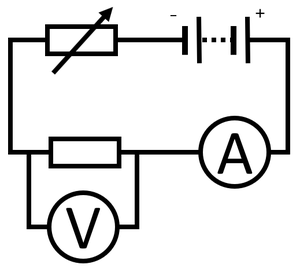
| + | #Connect an [[ammeter]] in [[Series Circuit|series]] with the [[resistor]] to measure [[Electrical Current|current]] through the [[resistor]]. | ||
| + | #Connect a [[voltmeter]] in [[Parallel Circuit|parallel]] with the [[resistor]] to measure the [[Potential Difference|potential difference]] across it. | ||
| + | #Use a [[Variable Resistor|variable resistor]] in [[Series Circuit|series]] with the [[resistor]] to vary the [[Potential Difference|potential difference]] across the [[resistor]]. | ||
| + | #Start with a [[Potential Difference|potential difference]] of zero and increase the [[Potential Difference|potential difference]] by an interval of 0.2V up to 2V. | ||
| + | #Recording the reading on the [[voltmeter]] and [[ammeter]]. | ||
| + | #Reverse the connections on the [[battery]] and repeat steps 4 and 5 to find the I-V relationship for negative [[Potential Difference|potential difference]] and [[Electrical Current|current]]. | ||
| + | |} | ||
Revision as of 18:14, 28 February 2019
Contents
Key Stage 3
Meaning
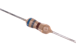
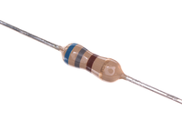
A picture of a resistor.
A resistor is a component in an electrical circuit which makes it difficult to electricity to pass through it.
About Resistors
- A resistor is a component designed to have a particular resistance.
- Resistors are added to circuits to control the current which will pass through for a certain potential difference.
- The greater the resistance of a resistor the smaller the current will be.
- The resistance of a resistor can be found by attaching an ammeter in series with the resistor and a voltmeter in parallel with the resistor.
- All components in a circuit act as resistors, including wires. The longer a wire the more resistance it will have to a current.
| A resistor. | The symbol for a resistor. |
Key Stage 4
Meaning

The symbol for a resistor.
A resistor is a component in an electrical circuit which makes it difficult to electricity to pass through it.
About Resistors
- A resistor is a component designed to have a particular resistance.
- Resistors are added to circuits to control the current which will pass through for a certain potential difference.
- The greater the resistance of a resistor the smaller the current will be.
- The resistance of a resistor can be found by attaching an ammeter in series with the resistor and a voltmeter in parallel with the resistor.
- All components in a circuit act as resistors, including wires. The longer a wire the more resistance it will have to a current.
Resistors in Series
- Adding resistors in series increases the resistance in the circuit.
- The resistance of each resistor can be added together.
| The resistance between points A and B is:
5Ω. | |
| The resistance between points A and B is:
2Ω + 5Ω = 7Ω | |
| The resistance between points A and B is:
2Ω + 5Ω + 9Ω = 16Ω |
Resistors in Parallel
NB: You only need to know what happens with identical resistors in parallel.
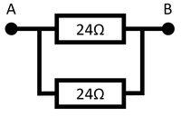
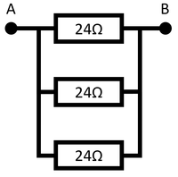
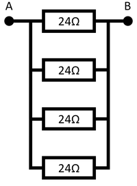
- When identical resistors are added in parallel there are more paths for the electricity so the resistance is reduced.
| Two identical resistors in Parallel circuit gives twice the number of paths, so has half the resistance.
The resistance between points A and B is 12Ω. |
Three identical resistors in Parallel circuit gives three times the number of paths, so has a third of the resistance.
The resistance between points A and B is 8Ω. |
Four identical resistors in Parallel circuit gives four times the number of paths, so has a quarter of the resistance.
The resistance between points A and B is 6Ω. |
IV Graph
Description
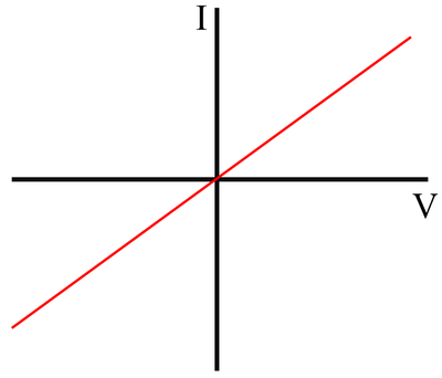
The IV Graph for a resistor shows that:
- As potential difference increases, increases.
- The relationship between potential difference and current is linear (the gradient is constant).
- The current is directly proportional to potential difference.
Explanation
- Resistors obey Ohm's Law so the "current through a resistor at constant temperature is directly proportional to the potential difference across the resistor."
Obtaining the IV Graph
|
