GCSE Physics Required Practical: Investigating Newton's Second Law
Contents
Key Stage 4
Meaning
Investigate the relationship between the force and acceleration of an object.
Experiment 1a: Light Gates Measuring Time and Velocity
Variables
- Independent Variable: The force applied to the object.
- Dependent Variable: The acceleration of the object.
- Control Variables: The mass of the object.
Method
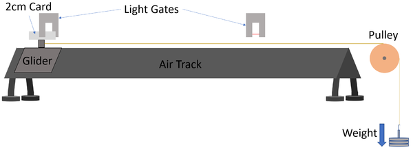
| A diagram of the apparatus used to investigate the effect of a force on the acceleration of an object. |
- Set up the equipment as shown in the diagram.
- Program into the light gates the length of the card on the glider as 2cm.
- Set the light gates to record the velocity through the gate and the time taken to travel between gates.
- Attach a known weight (approximately 0.1N) to wire.
- Release the weight and allow the glider to accelerate.
- Record the velocity through light gates 1 and 2 and the time taken between light gates.
- Use the equation \(a=\frac{v-u}{t}\) to calculate the acceleration of the glider.
- Repeat steps 3-6 adding 0.1N weight up to around 0.6N.
- Plot a scatter graph with the force of weight on the x-axis and the acceleration on the y-axis. The gradient of line of best fit will be the mass of the glider showing that \(F=ma\).
- Measure the mass of the glider using an electronic balance to compare results.
Improving Accuracy
- Calculate the weight added by measuring its mass using an electronic balance on a flat, level surface each time and using the equation \(W=mg\) with \(g=9.8\). This will give a more accurate knowledge of the weight rather than relying on the number printed on the weights.
- Ensure the glider remains motionless when no weight is attached. If the glider moves then adjust the feet on the air track until the glider remains stationary.
- Lubricate the pulley to reduce the force of friction which acts against the weight added.
Experiment 1b: Light Gates Measuring Displacement and Velocity
Variables
- Independent Variable: The force applied to the object.
- Dependent Variable: The acceleration of the object.
- Control Variables: The mass of the object.
Method
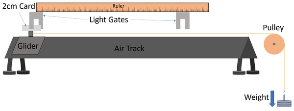
| A diagram of the apparatus used to investigate the effect of a force on the acceleration of an object. |
- Set up the equipment as shown in the diagram.
- Program into the light gates the length of the card on the glider as 2cm.
- Set the light gates to record the velocity through the gate.
- Measure and record the distance between the light gates using a ruler. This will be the displacement of the glider.
- Attach a known weight (approximately 0.1N) to wire.
- Release the weight and allow the glider to accelerate.
- Record the velocity through light gates 1 and 2.
- Use the equation \(v^2 - u^2=2as\) to calculate the acceleration of the glider.
- Repeat steps 4-7 adding 0.1N weight up to around 0.6N.
- Plot a scatter graph with the force of weight on the x-axis and the acceleration on the y-axis. The gradient of line of best fit will be the mass of the glider showing that \(F=ma\).
- Measure the mass of the glider using an electronic balance to compare results.
Improving Accuracy
- Calculate the weight added by measuring its mass using an electronic balance on a flat, level surface each time and using the equation \(W=mg\) with \(g=9.8\). This will give a more accurate knowledge of the weight rather than relying on the number printed on the weights.
- Ensure the glider remains motionless when no weight is attached. If the glider moves then adjust the feet on the air track until the glider remains stationary.
- Lubricate the pulley to reduce the force of friction which acts against the weight added.
Experiment 2: Trolley with Markings
Variables
- Independent Variable: The force applied to the object.
- Dependent Variable: The acceleration of the object.
- Control Variables: The mass of the object.
Method
| A diagram of the apparatus used to investigate the effect of a force on the acceleration of an object. |
- Set up the equipment as shown in the diagram.
- Adjust the gradient of the slope so that once pushed the trolley will move with a constant velocity.
- Attach a known weight (approximately 0.1N) to wire.
- Release the weight and start the stopwatch allowing the trolley to accelerate.
- Record the time on the stopwatch at each 10cm marker.
- Calculate the time difference between each 10cm marker.
- Use the equation \(v=s/t\) to calculate the average velocity between each 10cm marker.
- Use the equation \(a=\frac{v-u}{t}\) to calculate the acceleration of the trolley.
- Repeat steps 2-7 adding 0.1N weight up to around 0.6N.
- Plot a scatter graph with the force of weight on the x-axis and the acceleration on the y-axis. The gradient of line of best fit will be the mass of the glider showing that \(F=ma\).
- Measure the mass of the trolley using an electronic balance to compare results.
Improving Accuracy
- Calculate the weight added by measuring its mass using an electronic balance on a flat, level surface each time and using the equation \(W=mg\) with \(g=9.8\). This will give a more accurate knowledge of the weight rather than relying on the number printed on the weights.
- Adjust the friction compensated slope so that the trolley will move at constant velocity when no unbalanced force is applied.
- Lubricate the pulley to reduce the force of friction which acts against the weight added.
- Use light gates and a data logger to record the time taken between each marker.
- Use a smaller weight so that the trolley moves more slowly allowing the timing to be more accurate.
Improving Precision
- Use light gates and a data logger to record the time taken between each marker to reduce the random error caused by the human use of a stopwatch.


