GCSE Physics Required Practical: Investigating Resistance
Revision as of 14:38, 20 March 2019 by NRJC (talk | contribs) (Created page with "==Key Stage 4== ===Meaning=== Investigate the factors affecting the resistance in a circuit. ===Experiment 1a: Resistance and Length of a Wire==...")
Contents
Key Stage 4
Meaning
Investigate the factors affecting the resistance in a circuit.
Experiment 1a: Resistance and Length of a Wire
Variables
- Independent Variable: The length of a wire.
- Dependent Variable: The resistance of the wire.
- Control Variables: The thickness of the wire. The temperature of the wire. The current through the wire.
Method
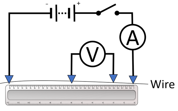
| A circuit diagram of the apparatus used to investigate the effect of the length of a wire on its resistance. |
- Set up the equipment as shown in the diagram.
- Place the clips for the voltmeter at 5cm apart on the wire.
- Close the switch and read and record the current from the ammeter.
- Read and record the potential difference on the voltmeter.
- Use the equation \(V=IR\) to calculate the resistance of this length of wire.
- Repeat steps 3 and 4 increasing the distance between the clips by an interval of 5cm a further 5 times.
- Plot a scatter graph with the length of wire on the x-axis and the resistance on the y-axis. The gradient of line of best fit will show the relationship between the length of the wire and its resistance.
Improving Accuracy
- Open the switch to stop the current from heating the wire when results are not being read. This improves accuracy because resistance is affected by the temperature of the wire.
- Ensure a low current throughout to reduce the heating effect of the current on the wire. This improves accuracy because resistance is affected by the temperature of the wire.
Improving Precision
- Use an ammeter with a greater resolution.
- Use a voltmeter with a greater resolution.
Experiment 1b: Resistance and Length of a Wire
Variables
- Independent Variable: The length of a wire.
- Dependent Variable: The resistance of the wire.
- Control Variables: The thickness of the wire. The temperature of the wire.
Method
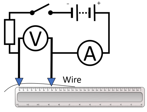
| A circuit diagram of the apparatus used to investigate the effect of the length of a wire on its resistance. |
- Set up the equipment as shown in the diagram.
- Close the switch.
- Place the clips for the circuit at 10cm apart on the wire.
- Close the switch.
- Read and record the potential difference on the voltmeter and the current from the ammeter.
- Use the equation \(V=IR\) to calculate the resistance of this length of wire.
- Repeat steps 4 and 5 increasing the distance between the clips by an interval of 10cm a further 5 times.
- Plot a scatter graph with the length of wire on the x-axis and the resistance on the y-axis. The gradient of line of best fit will show the relationship between the length of the wire and its resistance.
Improving Accuracy
- Open the switch to stop the current from heating the wire when results are not being read. This improves accuracy because resistance is affected by the temperature of the wire.
- Ensure a low current throughout to reduce the heating effect of the current on the wire. This improves accuracy because resistance is affected by the temperature of the wire.
- Use larger lengths of wire and a greater interval to reduce the heating effect of the current on the wire (since the current will be lower for longer lengths of wire. This improves accuracy because resistance is affected by the temperature of the wire.
Improving Precision
- Use an ammeter with a greater resolution.
- Use a voltmeter with a greater resolution.
Experiment 2: Resistors in Series
Variables
- Independent Variable: The number of identical resistors
- Dependent Variable: The resistance of the circuit.
- Control Variables: The resistance of the resistors. The potential difference across the resistors. The temperature of the resistors.
Method
| A circuit diagram of the apparatus used to investigate the effect of the number of resistors in series and the resistance in the circuit. | ||
- Connect a power supply and an ammeter in series with a resistor.
- Connect a voltmeter in parallel across the single resistor.
- Read and record the current from the ammeter and the potential difference from the voltmeter.
- Use the equation \(V=IR\) to calculate the resistance.
- Add an identical resistor in series and connect the voltmeter in parallel across both resistors.
- Repeat steps 3-5 for as many resistors as is available.
Improving Accuracy
- Open the switch to stop the current from heating the resistors when results are not being read. This improves accuracy because resistance is affected by the temperature of the resistors.
- Ensure a low current throughout to reduce the heating effect of the current on the resistors. This improves accuracy because resistance is affected by the temperature of the resistors.
Improving Precision
- Use an ammeter with a greater resolution.
- Use a voltmeter with a greater resolution.
Experiment 2: Resistors in Parallel
Variables
- Independent Variable: The number of identical resistors
- Dependent Variable: The resistance of the circuit.
- Control Variables: The resistance of the resistors. The potential difference across the resistors. The temperature of the resistors.
Method
| A circuit diagram of the apparatus used to investigate the effect of the number of resistors in series and the resistance in the circuit. | ||
- Connect a power supply and an ammeter in series with a resistor.
- Connect a voltmeter in parallel across the single resistor.
- Read and record the current from the ammeter and the potential difference from the voltmeter.
- Use the equation \(V=IR\) to calculate the resistance.
- Add an identical resistor in parallel and connect the voltmeter in parallel across both resistors.
- Repeat steps 3-5 for as many resistors as is available.
Improving Accuracy
- Open the switch to stop the current from heating the resistors when results are not being read. This improves accuracy because resistance is affected by the temperature of the resistors.
- Ensure a low current throughout to reduce the heating effect of the current on the resistors. This improves accuracy because resistance is affected by the temperature of the resistors.
Improving Precision
- Use an ammeter with a greater resolution.
- Use a voltmeter with a greater resolution.

